
- All
- Product Name
- Product Keyword
- Product Model
- Product Summary
- Product Description
- Multi Field Search
Views: 0 Author: Site Editor Publish Time: 2026-07-08 Origin: Site


Specifying a large-diameter structured-wall pipe requires moving beyond off-the-shelf dimension charts. Incomplete project data leads to conservative, over-engineered specifications or long-term structural liabilities. Because a Krah Pipe is highly customizable, manufacturers require specific site and operational data. You must provide exact inputs so they can optimize the design for your specific application. Custom profiles and variable stiffness classes mean guesswork has no place here. To receive an accurate technical proposal, project engineers and procurement teams must compile definitive data. You will need to gather comprehensive hydraulic, structural, and installation parameters. We will guide you through exactly what project data you need to collect today. You will learn how to accurately specify internal diameters, calculate load parameters, and define environmental constraints. Gathering this data ensures you get a resilient system tailored to your exact site requirements.
Traditional pipelines often rely on outer diameter specifications. This conventional approach creates significant problems when structural requirements force an increase in wall thickness. As the wall grows thicker inward, the internal flow area shrinks. Specifying a Krah Pipe solves this engineering challenge. You specify the internal diameter directly. Available sizes typically range from DN 300 up to DN 5000. Specifying the exact internal dimension guarantees you maintain your mathematically calculated flow rates. Civil engineers do not have to artificially oversize the outer diameter just to hit hydraulic targets. The internal flow channel remains completely constant. The manufacturer builds the required structural profile entirely on the outside of this defined flow area.
You must provide accurate and detailed flow data to the manufacturer. State the expected flow velocity clearly. Define the peak daily volume. Clarify the expected operating pressure. Gravity flow systems behave entirely differently than low-pressure applications. Low-pressure systems usually require a solid inner wall layer to handle outward hydrostatic forces. Gravity systems focus primarily on external ring stiffness to handle soil loads. Gathering this granular data ensures the final product handles peak storm events safely. It also ensures the system processes daily sanitary surges without backing up. Field experience shows engineers who supply accurate flow velocities prevent future scour or sedimentation issues.
Friction causes inevitable head loss in any pipeline network. You need to calculate required gradients highly accurately to maintain gravity flow. High-density polyethylene provides excellent hydraulic characteristics. You can assume a very favorable baseline internal surface roughness. The Manning’s n value typically hovers around 0.009 for these polymer systems. This ultra-smooth inner surface actively resists scaling. It heavily prevents biological buildup over decades of continuous use. Your internal flow dynamics remain highly consistent long after initial installation. Provide your strict head loss limits early. The manufacturer can then verify full hydraulic compliance before extrusion begins.
Burial depth directly controls the structural design of flexible pipelines. You must specify both the minimum and maximum cover depths precisely. Minimum cover data helps engineers mitigate dangerous live traffic loads. Shallow trenches transfer surface vibrations and point loads directly to the pipe crown. Maximum cover data determines the heavy dead soil weight. Deep burials require substantially higher ring stiffness to prevent excessive deflection. Manufacturers use this exact depth data to customize the profile dynamically along the pipeline route. They can beef up the profile for deep valleys. They can slim it down for shallow runs.
Flexible pipelines rely fundamentally on soil-structure interaction. The surrounding soil literally supports the structure. You must provide comprehensive geotechnical data. Identify the native soil modulus accurately. Specify the expected soil density. Outline the intended backfill material in detail. A highly compacted aggregate backfill requires less intrinsic pipe stiffness. Conversely, poor native soils might demand a much stronger custom profile. Do not guess native soil properties. Conduct proper core testing. The manufacturer needs real geotechnical numbers to run valid static calculations.
| Data Category | Specific Metric Needed | Primary Design Impact |
|---|---|---|
| Dead Loads | Maximum trench depth (meters) | Determines required Ring Stiffness (SN) |
| Live Loads | Traffic ratings (H20, HS20) | Dictates minimum cover and crown thickness |
| Geotechnical | Soil modulus (E') | Influences soil-structure interaction models |
| Hydrological | Maximum groundwater elevation | Drives buoyancy and anti-flotation measures |
Pipelines frequently run under active civil infrastructure. You must detail any expected traffic loads meticulously. Specify recognized standards like H20 or HS20 for highway applications. Railway beds and aircraft taxiways require even stricter loading calculations. Heavy surface loads transfer immense stress down into the trench zone. The manufacturer will adjust the wall profile specifically to absorb these dynamic forces. Failing to report heavy vehicle traffic often leads to premature crown deflection. Provide axle weight estimates if standard highway ratings do not apply to your industrial site.
Groundwater creates strong upward hydrostatic pressure. This phenomenon causes a severe risk of flotation for lightweight plastic systems. You must report the highest expected historical groundwater level. Engineers use this specific data for complex buoyancy calculations. They determine if you need mechanical anti-flotation measures. Sometimes, they simply design a heavier solid-wall profile to keep the system anchored safely in the trench. Ignoring seasonal water table fluctuations remains a common mistake. Always specify the worst-case flood scenario for accurate buoyancy prevention.
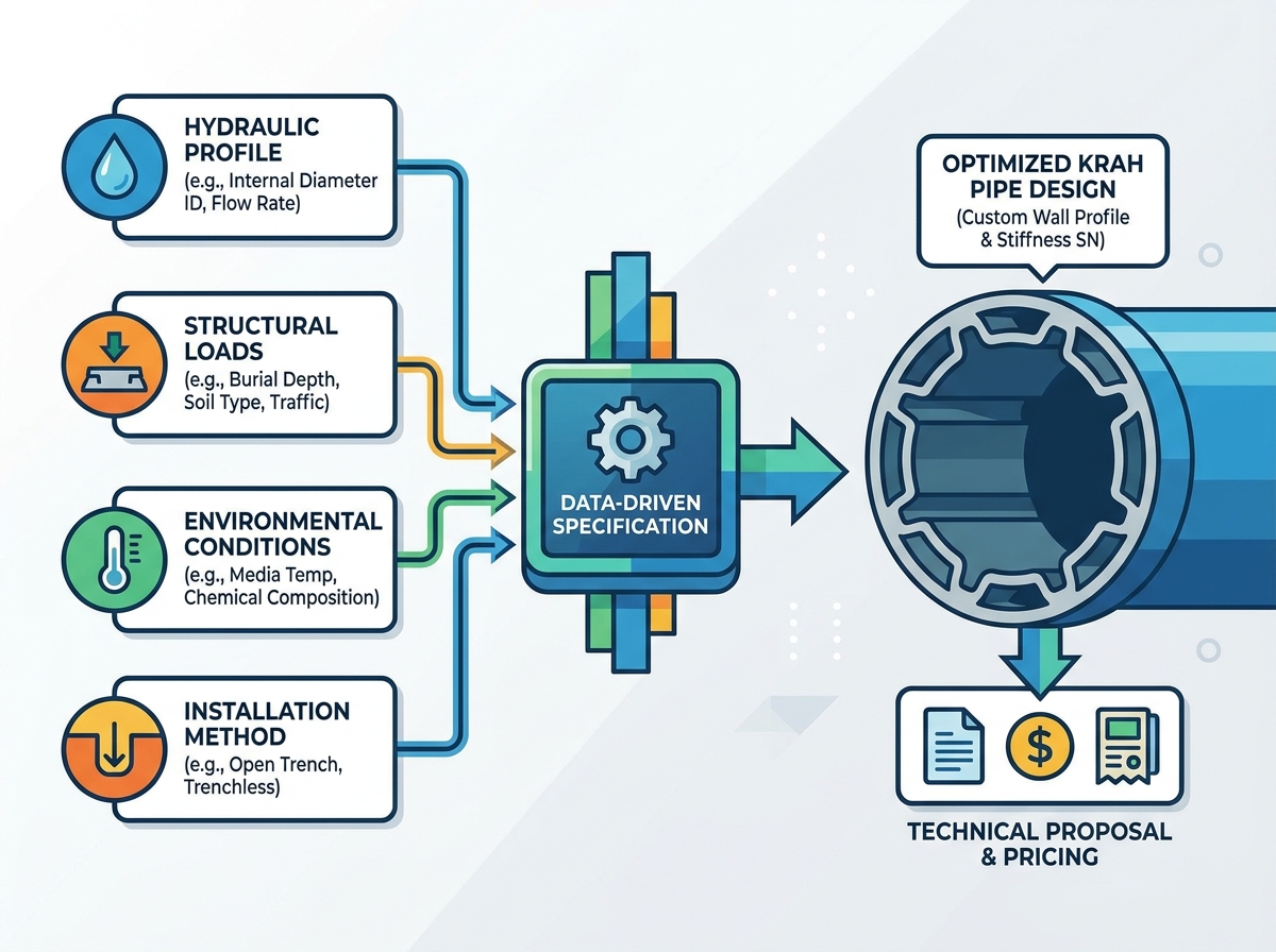
The fluid you transport dictates critical material choices. You must specify the exact media composition thoroughly. Sanitary sewage behaves differently than raw industrial effluent. Stormwater carries unique abrasive debris loads. Abrasive slurries in mining applications cause rapid internal wear. You must detail the presence of suspended solids. Manufacturers can add specific interior wear layers if they know about these abrasive conditions. Providing a clear breakdown of the effluent ensures the interior wall survives its intended design life.
Polymer structural properties are highly temperature-dependent. You need to outline the entire operating temperature range clearly. Include both the internal media temperature and ambient environmental extremes. Continuous high-temperature flows weaken the polymer structure over time. A Krah Pipe handles elevated temperatures safely if designed correctly from the start. Sustained high temperatures strictly require specific design adjustments. Engineers will apply necessary thermal derating factors to their static calculations. This ensures the ring stiffness remains adequate even when the plastic softens slightly under extreme heat.
Common Mistake: Many engineers ignore ambient summer temperatures during above-ground storage phases. Black polymer absorbs intense solar radiation. This thermal expansion alters installation tolerances. Always specify if you plan to store materials in direct desert sunlight before burial.
Industrial applications frequently transport harsh chemical compounds. You must provide a comprehensive chemical analysis of the effluent. State the expected pH range clearly. Identify any reactive hydrocarbons or aggressive solvents. Polyethylene offers exceptional baseline chemical resistance naturally. However, highly reactive industrial flows might require co-extruded functional layers for absolute safety. Giving manufacturers this exact data guarantees long-term chemical compliance. It prevents sudden catastrophic failures caused by chemical embrittlement decades later.
Your chosen installation technique fundamentally changes the required structural design. Tell the manufacturer exactly how you plan to lay the line. Different civil methods impose vastly different installation stresses on the structure.
Here are the most common methodologies you need to define clearly:
Delivery constraints influence major manufacturing decisions. You must define your site logistics early in the process. Standard manufacturing lengths usually hit 6 meters or 9 meters. Transportation limits might force you to request shorter lengths. Winding mountain roads simply cannot accommodate massive oversized truckloads. Additionally, urban trench boxes often limit the physical length you can safely install at once. Specify your rigid length constraints so the factory can optimize their production batches accordingly. This prevents costly on-site cutting and wasted material.
Connections represent the most vulnerable point of any pipeline network. You need to specify your preferred jointing technique. Integrated electrofusion creates a homogeneous, completely leak-proof system. It works perfectly for low-pressure applications or highly sensitive environmental areas. Alternatively, spigot-and-socket connections utilize reliable elastomeric seals. These mechanical seals assemble very quickly in the trench. They are entirely sufficient for standard gravity drainage networks. Providing your true pressure ratings allows engineers to recommend the safest, most efficient jointing method.
Strict regulatory compliance protects your civil investment. You must specify exactly which standards govern your local project. Different global regions rely on different engineering frameworks. You should mention standards like DIN 16961 for structured-wall thermoplastics. EN 13476 dictates strict requirements for unplasticized drainage systems. ISO 9969 defines the highly precise method for calculating ring stiffness. Aligning your data inputs directly with these recognized standards ensures seamless municipal approvals. It also provides a clear benchmark for quality control during factory acceptance testing.
Submitting accurate data triggers a detailed, highly technical engineering response. You should expect specific deliverables back from the manufacturer. They will generate comprehensive static calculation reports. These detailed reports validate the proposed stiffness classes mathematically. You will also receive accurate AutoCAD or BIM models for your network. Finally, expect heavily detailed jointing protocols. These essential documents guide your on-site contractors through perfectly safe assembly procedures. Review these deliverables carefully to ensure they match your original data inputs.
Engineers often demand uniformly high stiffness across an entire network. Requesting SN16 everywhere feels incredibly safe. However, this lazy approach creates unnecessary, massive material costs. Customized profiling offers a much smarter approach. A Krah Pipe changes profile along the route based precisely on varying depths. You achieve the exact same safety factor. You drastically reduce overall material usage. You save substantial project capital. Trust the granular static calculations rather than defaulting to conservative extremes. Let the data drive the profile.
Accurate specification remains a highly collaborative engineering process. It relies fundamentally on precise site and operational data. You cannot afford to guess hydraulic limits or structural loads. The upfront effort of gathering comprehensive data directly translates to a more resilient system. Detailed geotechnical inputs and strict thermal parameters prevent premature underground failures. You ultimately build a highly durable, cost-effective pipeline asset. Standardized data collection streamlines the entire procurement cycle. Download a standardized data collection sheet today. Contact technical sales immediately for a dedicated project consultation.
A: Specifying by ID ensures consistent hydraulic capacity regardless of the required wall thickness. When you need a thicker wall for structural integrity, the outer diameter grows instead. This guarantees your internal flow channel never shrinks. It eliminates the need to oversize traditional pipes just to hit specific flow targets.
A: These systems generally handle up to 60°C continuously. They can tolerate short thermal peaks up to 80°C safely. However, exact limits depend heavily on internal system pressure and total lifespan requirements. High sustained temperatures strictly require structural derating factors. You must provide accurate thermal data so engineers can adjust the profile.
A: No. The specifying engineer only provides the exact load, depth, and pressure data. The manufacturer utilizes proprietary software to calculate the complex forces. They will propose the optimal wall profile automatically. This collaborative process ensures you get the most efficient, mathematically validated structure.
A: Lead times typically range from a few days to a couple of weeks. It heavily depends on project scale and overall complexity. Highly customized systems requiring advanced static calculations take slightly longer. Providing a complete, accurate data set upfront drastically reduces this turnaround time. It eliminates endless engineering revisions.


